Two button control of the servo
- Keith Marange

- Feb 9, 2019
- 2 min read
Updated: Feb 21, 2019
In this blog post, I will explain how Matthew and I were finally able to precisely control movement of the servo using the electronic circuit concepts.
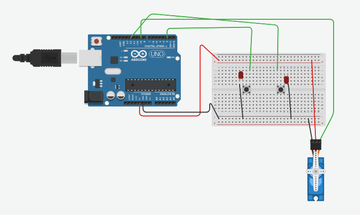
Circuit

Code
#include <Servo.h>
#include <SoftwareSerial.h>
int angle = 90;
int anglespeed = 5; // how many degrees will the servo move per millisecond
Servo servo_9; // name/definition of the servo
#define Left 2 // left button
#define Right 12 // right button
void setup()
{
Serial.begin(9600);
servo_9.attach(9); //servo connected to pin #9
servo_9.write(angle); //initial angle of the servo
pinMode(Left, INPUT_PULLUP); // left button is connected to defined pin 2(Left)
pinMode(Right, INPUT_PULLUP); // right button is connected to defined pin 12(Right)
}
The above section, as described by the name, is the setup of all the components that are connected to the Arduino with their corresponding pin or input source.
The use of INPUT_PULLUP: This code has been used to make the pin behave like a resistor that enables a High state or “1” signal to be recognized by the Arduino. This allows to maintain the High state within the circuit, in order to recognize any change of state produced by the connected peripherals , e.g. when the button is pressed it changes the signal to Low state and then triggers a movement in the servo.
void loop()
{
while( digitalRead(Left) == LOW){
if (angle >= 0){
angle = angle + anglespeed;
}
else{
angle = 0;
}
servo_9.write(angle);
Serial.print(" Moved to:");
Serial.print(angle);
Serial.print("degrees ");
Serial.print('\n');
}
delay(15);
The above code is the section that allows the movement of the servo when the left button is pressed. When the button is pressed the signal will change into a LOW state, this will trigger the command while and subsequently the sum that will define the new angle of the servo. The command else is used to assure that the value will not go lower than 0 degrees, as this is the limit of this range of movement. Finally the command servo_9.write(angle) will proceed to move the servo to the new angle.
The commands Serial.print(“ “) are used to be able to visualize the data in the Serial Monitor.
while( digitalRead(Right) == LOW){
if (angle <= 180){
angle = angle - anglespeed;
}
if (angle > 180){
angle = 180;
}
servo_9.write(angle);
Serial.print("Moved to:");
Serial.print(angle);
Serial.print("degrees");
Serial.print('\n');
}
}
Similar to the previous explanation.
Problems
At the beginning the circuit didn´t work correctly, it was thought it was due to a problem with the code. But through continuous testing it was determined that the circuit was at failure. The connection of the buttons have to be set in a way in which the circuit can be completed, however it is not possible to determine this visually on TinkerCad. Therefore to see the correct connection of the circuit, the testing each side of the button with a LED connected to the circuit was performed. This allowed to see the correct connection, as the LED will turn on (slightly) when connected properly.
Miguel Li


Comments